
| % slope | Depth increase inches (cm) | % slope | Depth increase inches (cm) |
|---|---|---|---|
| 1 | 1 (2) | 16 | 19 (48) |
| 2 | 2 (5) | 17 | 20 (51) |
| 3 | 4 (10) | 18 | 21 (53) |
| 4 | 5 (13) | 19 | 22 (56) |
| 5 | 6 (15) | 20 | 24 (61) |
| 6 | 7 (18) | 21 | 25 (64) |
| 7 | 8 (20) | 22 | 26 (66) |
| 8 | 10 (25) | 23 | 27 (69) |
| 9 | 11(28) | 24 | 28 (71) |
| 10 | 12 (30) | 25 | 29 (74) |
| 11 | 13 (33) | 26 | 30 (76) |
| 12 | 14 (36) | 27 | 31 (79) |
| 13 | 15 (38) | 28 | 32 (81) |
| 14 | 17 (43) | 29 | 33 (84) |
| 15 | 18 (46) | 30 | 34 (86) |
DCI DigiGuide User Manual
2026.04.25- Only operate your DCI guidance system in accordance with the operating instructions for your system.
- Serious injury and death, as well as property damage, can result if underground drilling equipment strikes a natural gas line, high-voltage electrical cable, or other utility.
- Work slowdowns and cost overruns can occur if you do not use your system correctly.
- Properly calibrate your DCI guidance system anytime you change frequencies, transmitters, or drill heads and validate the calibration before every drilling project. If you fail to do so, depth readings will likely be inaccurate.
- Interference can lead to inaccurate depth readings and/or interruption of data. See "Special Notes About Interference" for more details.
- DCI guidance systems are used to locate and guide the transmitter (housing) underground. They cannot be used to locate underground utilities.
- Failure to find the front and rear locate points can lead to inaccuracies which may result in drilling off-path and striking an underground utility.
- The locate line on a DCI locator does not indicate the position of the drill head. DCI locators track the transmitter in its housing, which sits behind the drill bit. Also, when drilling steep and/or deep, the locate line may indicate a position behind or ahead of the transmitter. Please see "Steep and Deep" under Advanced Topics for important information about accurately locating the drill head when drilling steep and/or deep.
- Ensure that all underground utilities have been located, exposed, and/or accurately marked prior to drilling. Follow all proper safety precautions, such as potholing.
- DCI equipment is not explosion-proof and should never be used near flammable or explosive substances.
- Wear jobsite protective/safety clothing such as dielectric boots, gloves, hard hat, high-visibility vest, and safety glasses.
- Install transmitters into the drill housing as soon as possible after powering on. If you can't, unscrew the cap to power off the transmitter until you can install the transmitter into the drill housing to reduce RF exposure.
- Comply with federal, state, and local governmental regulations (such as OSHA) and all other customary or required safety precautions.
If you have any questions about the operation of your guidance system, please contact DCI Customer Service for assistance.
While DCI guidance systems provide you with technology to combat active interference (and passive interference, with the Sub-K Rebar transmitter), no guidance system is immune to all interference.
Interference can lead to inaccurate depth readings and/or interruption or loss of data. Never rely on data that does not display quickly and/or remain stable.
The Falcon frequency optimizer selects frequencies based on measured interference at a specific time and location.
Interference levels change with time and with even minor changes in location. The frequency optimizer is not a substitute for prudent operator judgment. If performance drops while drilling, consider switching to the other selected band (not available on the Falcon F1) or use Max Mode.
An A on the screen can indicate signal Attenuation due to the presence of excessive interference, which can make depth readings inaccurate. Attenuation is normal in shallow depths less than 8 ft (2.4 m). If the signal strength is also flashing; this indicates extreme interference. Depth and locate points may be compromised and the locator will not calibrate.
Interference is classified as either active (generating electro-magnetic signals) or passive (material that can conduct or block electro-magnetic signals). Sources of interference may include:
Active
- Traffic signal loops
- Buried dog fences
- Cathodic protection
- Radio communications
- Security systems
- Microwave towers
- Power, phone, fiber-trace and cable TV lines
Passive
- Metal pipes
- Rebar
- Trench plates
- Chain-link fences
- Vehicles
- Saltwater/salt domes
- Conductive earth, such as iron ore
If you have any questions about the operation of your guidance system, please contact DCI Customer Service for assistance.
System working altitude: up to 6562 ft (2000m).
Storage and transportation temperature: -40° to 149°F (-40° to 65°C).
Operation may be compromised if the equipment is subjected to conditions outside these specified limits.
Ship in original carrying case or packaging of sufficient durability to prevent mechanical shock to equipment during transportation.
If you have any questions about the operation of your guidance system, please contact DCI Customer Service for assistance.
Remove the batteries from all system components during shipping and prolonged storage. Failure to do so may result in battery leakage, which may lead to risk of explosion, health risks, and/or damage.
Store and transport batteries using a suitable protective case that will keep batteries safely isolated from one another. Failure to do so may result in short circuits, which may lead to hazardous conditions including fire.
Lithium-ion batteries must be packaged and shipped by trained and certified personnel only. Never ship damaged batteries.
If you have any questions about the operation of your guidance system, please contact DCI Customer Service for assistance. Connect to DCI Customer Service with the Contact link in the DigiGuide App or find a list of offices in the back of any printed DigiGuide manual and on the DCI website: digital-control.com.
If you plan to store the battery packs for any period of time, please follow these guidelines:
Store and transport batteries using a suitable protective case that will keep batteries safely isolated from one another. Failure to do so may result in short circuits which may lead to hazardous conditions including fire.
Do not store the battery pack at temperatures greater than 113° F (45°C).
Do not store the battery pack in a fully discharged state.
Do not store the battery pack in the battery charger.
Do not store multiple batteries together where their terminals or other loose conductive materials may contact one another and cause a short circuit.
Never ship damaged batteries.
If a lithium-ion battery pack will be stored for an extended period of time, pre-charge the battery to a charge level of 30% to 50% (two or three LEDs illuminated on the meter).
Do not store the battery pack for more than one year unless it is periodically recharged to the 30% to 50% level.
Lithium batteries are regulated by UN3480 and UN3481 lithium-ion batteries.
Lithium batteries are considered Class 9 Miscellaneous Dangerous Goods under International Air Transportation Association (IATA) regulations; IATA regulation and Ground Transportation regulations 49 CFR 172 and 174 apply. These batteries must be packaged and shipped by trained and certified personnel only. Never ship damaged batteries.
This symbol on equipment indicates that the equipment must not be disposed of with your other household waste.
Instead, it is your responsibility to dispose of such equipment at a designated collection point for the recycling of batteries or electrical and electronic equipment. If the equipment contains a banned substance, the label will show the pollutant (Cd = Cadmium; Hg = Mercury; Pb = Lead) near this symbol.
Before recycling, ensure batteries are discharged or the terminals are covered with adhesive tape to prevent shorting.
The separate collection and recycling of your waste equipment at the time of disposal will help conserve natural resources and ensure it is recycled in a manner that protects human health and the environment.
For more information about where you can drop off your waste equipment for recycling, please contact your local city office, your household waste disposal service, or the shop where you purchased the equipment.
U.S.: Contact The Battery Network’s Drop-off Locator at 1-877-2-RECYCLE or visit www.batterynetwork.org.
Ce symbole figurant sur l'équipement indique qu'il ne faut pas le jeter avec les ordures ménagères.
Il vous incombe en effet d'éliminer ce type d'équipement en l'amenant à un site de récupération désigné pour le recyclage des batteries/piles ou d'appareils électriques et électroniques. Si le matériel contient une substance interdite, l'étiquette indiquera le polluant (Cd = cadmium ; Hg = mercure ; Pb = plomb) à côté de ce symbole. Avant de recycler les batteries, assurez-vous qu'elles sont déchargées ou que les bornes sont recouvertes d'un ruban adhésif pour éviter les courts-circuits. La collecte séparée et le recyclage de votre matériel usagé au moment de l'élimination permettront de conserver les ressources naturelles et de veiller à un recyclage en bonne et due forme, qui protège la santé humaine et l'environnement. Pour plus d'informations sur les sites où vous pouvez déposer votre matériel usagé à recycler, veuillez contacter les autorités municipales, votre service d'élimination des déchets ménagers ou le lieu d'achat du matériel.
When powered on, the Aurora automatically displays its Home screen.
The Aurora has a touchscreen to navigate the menu system and select options. Use the soft pad of your fingertip to tap the display or use gloves with a touchscreen-compatible fingertip. Never use a fingernail or foreign object.
The Aurora touchscreen features a taskbar at the bottom. The taskbar shows any open applications as well as an icon for the Main menu.
The Aurora also has shortcuts directly to key features. For example, to change the telemetry channel or locator type, hold your finger on the telemetry channel label at the top of the screen. Aurora opens the appropriate Settings window in the Main menu.
To return to the Home screen, tap Home in the taskbar.
The Aurora display has four applications preinstalled.
- Configure - Manages bore plans
- XR - Change bands with pre-programmed roll sequences
- LWD Live - Logs rods while drilling
- Strip Chart - Monitors and graphs fluid pressure, temperature, and pull-back tension data over time
- Applications tab
- Configure app
- XR app
- LWD Live app
- Strip Charts app
- Settings tab
- Device settings
- Connectivity settings
- Alarm settings
- Pitch History
- Locator model, telemetry channel, and region
- Peripheral setup
- Software updates
- Help tab
- Safety Warnings
- Information
- Power On Self Tests
- Help
- Instructional Videos
- Taskbar
- Home
- Main Menu
- Distance to the nearest waypoint
- Distance to the nearest utility
- Estimated projected depth (3 rods out in this example)
- Terrain
- R1 Boreplan (solid gray line)
- Drilled path (solid blue line)
- Projected path (broken blue line)
- Scaling the chart slider
- LWD Tab
- Rod number
- Pitch
- Depth
- Distance
- Time per rod
- Live data
The shaded area in this graph indicates the five rods currently displayed in the table below it. Swipe the table left or right to see data for other rods in the bore.
- Topography
- Drill path
- Area of graph represented in table
- Home
- Zoom out
- 5-rod view (zooms graph to shaded area)
- Delete rod
- Add rod
- Rod number
- Pitch
- Depth
- Distance
- Time per rod
Stuff You Should Know

Registering your equipment activates the product warranty.
Registering also allows us to contact you if it is recovered after being lost or stolen.
If you want to enable the Lock Out Capability (LOC) feature, contact DCI support.
See the DCI website for warranty terms and conditions.
Contact your authorized DCI dealer or DCI to register your equipment.
You will need the equipment serial number and your company contact information.
Here’s where to find your serial number:
- Locator: in the battery compartment
- Transmitter: engraved on the steel body
- Remote display: decal on the back
Connect Aurora to the drill rig power source.
Verify the locator type shown at the top of the screen (such as FF5 or FF2) matches your locator.
If needed, tap and hold the locator type to change it, otherwise continue to Jobsite Setup to verify locator data displays.
Tap Main Menu.
Things You Should Know
- To download the latest software, click here, and then click Download on the top of the Dropbox page to download the files to your computer. The files will be saved in a zip file named "AuroraUpdate.zip."
- Unzip the folder by right-clicking on it, clicking Extract All, selecting the same location, and then clicking Extract.Warning: "AuroraUpdate" must be the folder name. If you downloaded it more than once, remove the (#).
- Copy the unzipped "AuroraUpdate" folder to a USB flash drive (min 2 GB).
On the Settings tab, tap Updates.
Tap USB Refresh.
The Aurora Remote update is highlighted in blue.
Insert the USB flash drive with the software update into the Aurora.
Tap Install.
Watch video on YouTube:
How To: Update Your Aurora Remote Display - English (0:40 min.)
Ensure antenna and display connectors are free of debris and that the antenna pin is straight and intact.
Connect the telemetry antenna.
For long whip only – Mount antenna as high as possible and on a metal surface for maximum signal reception.
With the transmitter and locator paired and powered on, verify that data like pitch, roll, and temperature displays on the Home screen.
Roll the transmitter to ensure the roll clock moves correspondingly.
Before you start
To transfer an R1 bore plan to an Aurora Display, you will need:
- R1 software version: 2.3 or later
- Aurora display software version: 2.5 or later
- An R1 Bluetooth adapter for the Aurora display (not included)
- An R1 subscription on myDCI for the R1 with the bore plan
If you would like to get a Bluetooth adapter, you can contact your dealer or DCI Customer Support.
For more information about subscriptions, see the article "Add or manage subscriptions" in the Initial Setup chapter.
Open the job you want to send.
The job needs to be finished before it can be sent.
Tap Upload.
Tap Send to Aurora.
The Aurora display must be on and with the Bluetooth adapter inserted. The message, "Ready to Receive" displays in the Aurora display taskbar.
You can track the progress of the transfer on both the R1 App and on the Aurora display.
When the transfer is complete, tap OK.
Before You Start
The Aurora display must have software version 2.5 or later and have the R1 Bluetooth adapter inserted.
The message, "Ready to Receive" displays in the Aurora display taskbar.
In the R1 app, select the job to be transferred and then tap Export.
For step-by-step instructions, see the article "Transfer a bore plan to an Aurora Display" in the Initial Setup chapter of the Aurora manual.
To start the job with a R1 bore plan. On the Plans tab, tap New Bore next to the selected bore plan.
Review the bore plan, and then tap OK.
On this screen:
- Confirm the rod length
- Confirm the first rod length (0 rod in LWD)
- How many projected rods to show in chart
Tap OK to continue.
The Rod Length is the defined in the R1 App. To change the Rod Length on the R1 for future plans (or to update this plan) see the article, "Set Default Drill Parameters" in the Initial Setup chapter of the R1 manual.
A live pitch is required. Ensure transmitter and locator are powered on and calibrated before logging data. Ensure the Aurora remote is receiving data.
Confirm the target or planned pitch for the first rod of the job. This is the same as rod 0 in LWD.
If you starting a bore in a pit, review the article "Start a new bore in a pit" in the Advanced Topics chapter.
To view an active job and start logging the bore, tap Start on the LWD Live Home screen.
Upon starting a new bore, the table will be divided into logged rods (1), the current rod (2), and planned rods (3). As you log rods, the new data (4) will replace the plan and the highlight column will move to the next projected rod.
- Logged Rod
- Current Rod
- Next rod of the plan.
- Time per Rod
You can scroll to the right to see more of the planned rods.
On the LWD Live tab, tap New Bore.
Tap in the Name field, enter a unique file name, and tap OK.
Position the drill head for the first data point with the housing slots halfway in the ground.
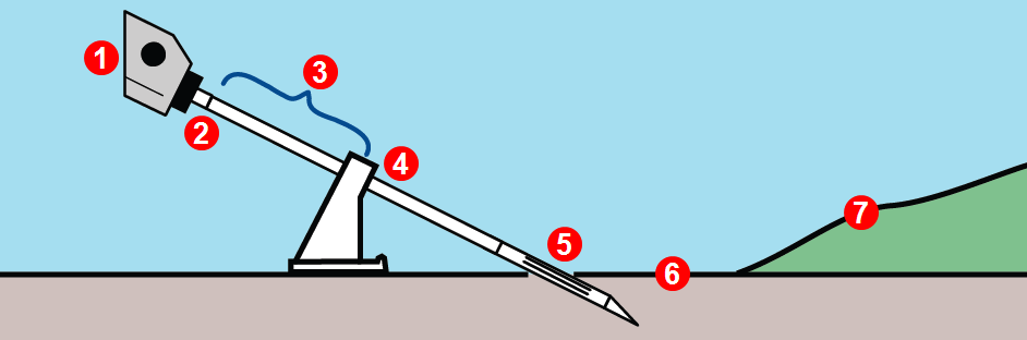
- Drill
- Top of rod
- First rod length
- Vice
- Slots in housing halfway in ground
- Zero elevation reference line
- Surface of ground
Enter optional Notes and edit the Rod Length and First Rod Length values if needed.
- Rod length
- First rod length
- Planned rods to display
Tap Continue.
Upon starting a new bore, the table will be blank except for the current rod, which displays at the right side. The only transmitter data displayed for the first rod is pitch.
- Current rod
Before You Start

This article assumes that the bore plan was created in the R1 app and then transferred to the Aurora remote display. For instructions, see the DCI DigiGuide app article "Transfer Plan to Aurora Display" in the Jobsite Setup chapter in the Aurora Display manual.
Three key best practices
To get the best results when using the R1 bore plans on the Aurora, there are three key points to consider.
- Match the entry point of the bore to the R1 plan
- Log the first rod accurately
- Log depth data at the Locate Line over the transmitter housing
Match the entry point of the bore to the R1 plan
It is critical that the entry point from the R1 plan and the physical entry of the drill head into the ground are “the same”. In other words, if the entry point from the plan is 20 feet from the edge of a road, and the machine was set up where the drill head enters the ground 25 feet from the road, the plan and the data logged in LWD Live will never match.
If the machine cannot be moved, then edit the entry point in the R1 plan to move it 5 feet further from the road and then retransfer the plan to the Aurora.
For details, see the chapter "Use Terrain Data" in the DCI DigiGuide App TeraTrak R1 manual.
Log the first rod accurately
The workflow walks you through the necessary steps, but it is key that the first data point is logged when the drill head is halfway into the ground. The image from the Configure app illustrates how to do that.
- Rod length
- First rod length
- Number of projected rods
The app will only allow you to proceed if you have a pitch reading from the transmitter.
Log depth data over the transmitter housing at the Locate Line
The R1 bore plan displays the planned depth and pitch at the end of the rod. The R1 app calculates the planned depth from the depth reading over the transmitter housing. It is therefore essential that when logging data in LWD Live, the locator takes a depth reading at the Locate Line over the transmitter housing.
If depth reading can not be taken over the drill housing (if there is an obstruction for example), log the pitch only.
To record only the slope, tap the green depth button so it turns orange before tapping the check mark. This creates a blank survey point on the graph (if R1 plane data is not used).
If no depth reading is available, the depth button is already orange.
Data displays on the Home screen as soon as the locator receives data from a transmitter.
- Status bar
- Locator type / Telemetry channel
- Telemetry signal strength
- (This feature is disabled and not available)
- Time
- Transmitter (Tx) battery
- Tx pitch
- Tx roll
- Tx temp and temp history
- Fluid pressure and FP history (if applicable)
- Logging
- Taskbar with Home icon active
When the locator takes a depth reading at the Locate Line (LL), Aurora displays transmitter depth and pitch information beside the roll indicator.
- Depth data timer
- HAG On
- Current pitch
- Depth
- Pitch at time of reading
The blue highlighting remains until the data is ten seconds old, then reverts to white. The data remains for five minutes, which is counted by the timer located in the locator icon. A new depth reading will restart the timer.
If HAG (Height-Above-Ground) is not on, the locator will be on the green terrain line.
When the locator takes a depth reading at the Front Locate Point (FLP), the predicted depth * and distance displays beside and below the roll indicator.
- Predicted depth data timer
- Current pitch
- Predicted depth
- Pitch at time of reading
- Horizontal distance between transmitter and FLP
The blue highlighting remains until the data is ten seconds old, then reverts to white. The data remains for five minutes, which is counted by the timer located in the locator icon. A new depth reading will restart the timer.
If HAG is not on, the locator will be on the green terrain line.
A depth reading taken at the Rear Locate Point (RLP) will still display a predicted depth, but because the locator cannot distinguish between FLP and RLP, it will be inaccurate.
The Predicted Depth screen displays when the trigger is held with the locator at the Front Locate Point (FLP). The predicted depth is how deep the transmitter is calculated to be when it reaches the front locate point if it continues on its current path. The predicted depth will also display when the locator is at the Rear Locate Point (RLP), but it will not be correct.
Switching bands on the transmitter may provide better data, better depth, and/or better locate results as interference conditions change.
This procedure requires roll data from the transmitter. If you need to change bands on the transmitter but do not have roll data, see Changing Bands Using RRS Method under Advanced Topics.
Before you start, either disable Roll Offset or note the clock position of the Roll Offset before you begin this procedure.
On the Main menu, tap XR.
Tap XR in the task bar.
Tap Start for 10-2-7 roll method.
If Roll Offset has been enabled, either disable it or enter the clock position noted before starting.
Tap Start to begin on-screen instructions.
Rotate until the transmitter clock falls within the flashing blue zone indicated on the screen. Wait until timer expires. Repeat until 10-2-7 sequence is completed.
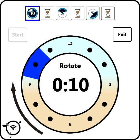
If any rotation is not completed within the prescribed time, or if any rotation continues for more than one full revolution, the transmitter band change is canceled.
When the procedure is finished, the transmitter changes bands, causing transmitter data to disappear. This may cause a failure notice to appear even if the band change was successful. Always rely on the locator operator to verify a band change.
Data will not disappear after a band change when using a Falcon Sub-k Rebar transmitter.
The locator operator should now change to the other paired and calibrated band.
If the locator operator has not calibrated the second band, depth readings will not be correct.
Tap Exit, then Main menu.
Tap XR again in the Applications tab to close it.
Tap Home to view transmitter data.
If Roll Offset was disabled before starting, re-enable it before continuing.
With the locator within range of the transmitter, log the first data point (Rod 0) by tapping Add Rod.
For Rod 0, only pitch is available.
Tap Continue.
Drill to the end of the first rod. Once data appears in the Current Rod column, tap Add Rod to log the first complete rod (Rod 1).
- Rod 0
- Current rod
Tap Continue to log the rod.
As you continue drilling, tap Add Rod each time data you want to record appears in the Current Rod column. Then select the green check mark to log the data.
- Logged topography
- Projected topography
- Pitch
- Depth
- Logged bore
- Projected bore
- Current Rod column
- Partial rod options (select before logging)
If the data in the Current Rod column appears inaccurate, you may wish to request another depth reading from the locator before recording. Optionally, you may choose to log a pitch only or blank rod. See next steps.
It is never recommended to drill without good data.
To log pitch only, tap the green depth button so it turns orange before tapping the check mark. This results in a blank topography point on the graph (when not using R1 plan data).
If a depth reading is not available, the depth button will already be orange.
To log a blank rod, tap the green pitch button so it and the depth button turn orange before tapping the check mark. This will result in a blank point on both the topography and bore graphs.
In rare cases while using an R1 boreplan, a depth value being logged is "impossible" It can still be entered but it will appear in gray italicized text with a question mark "?" in the cell.
Using Recent Data
If the Add Rod button is not pressed within 10 seconds of a depth reading, you may still recall the most recent depth and pitch values.
Press the Add Rod button and then tap the Recent Data button.
The pitch and depth buttons will turn green.
Tap Continue to log the rod.
The last rod is often a partial rod. Choose the appropriate partial rod options before tapping Continue.
To delete the last rod (required if it was pulled back or accidentally recorded twice), tap Delete Rod
then Continue to confirm.
Deleted rods are visible for reference so you can compare the rods that were drilled in against the rods that were pulled back.
Tap on any column of rod data in the table to see detail for that rod.
- Drill elevation
- Timestamp
- Topography height above drill
- Topography
- Depth
- Rod number
- Data at start of rod
- Data at end of rod
- Difference between start and end of rod
Tap Cancel to return to the five-rod table.
Hold the power/screen lock button on the side for approximately two seconds to lock the screen for cleaning.
Use a microfiber or soft cotton cloth with water and a mild liquid detergent to clean the screen and case.
Commercial cleaning products will damage the screen’s protective coating.
Do not pressure wash.
Carefully remove and store the antenna in the carry case to prevent damage.
If the remote display is installed in the drill console, place the protective plastic cover over the screen.
If the display can be removed from the rig, store it in the system carry case away from impact, moisture, and excessive temperatures.
Storage and transportation temperature must remain within -40° – 149°F (-40° – 65°C).
Tap Main menu.
On the Settings tab, tap Device.
Tap Calendar and use the drop-down menus to set the date, time, and time zone.
Tap to return to the Home screen.
Tap Main menu.
On the Settings tab, tap Device.
Tap the Framing Square icon and use the drop-down menus to set units for temperature, distance, pitch, pressure (for fluid pressure transmitters), and force (for TensiTrak only).
Tap to return to the Home screen.
Tap Main menu.
Tap the Locator.
Use the drop-down menu to select your locator.
Tap to return to the Home screen.
Switching bands on the transmitter may provide better data, better depth, and/or better locate results as interference conditions change.
This procedure requires roll data from the transmitter. If you need to change bands on the transmitter but do not have roll data, see Changing Bands Using RRS Method under Advanced Topics.
Roll offset must be disabled before changing bands.
Position the transmitter at 10:00 (±1 clock position, or CP) and remain there for 10–18 seconds.
Rotate the transmitter clockwise to its 2:00 position (±1 CP) within 10 seconds and remain there for 10–18 seconds.
If any rotation is not completed within the prescribed time, or if any rotation continues for more than one full revolution, the transmitter band change is canceled.
Rotate the transmitter clockwise to its 7:00 position (±1 CP) within 10 seconds and wait.
When the procedure is finished, the transmitter changes bands, causing transmitter data to disappear.
Data will not disappear after a band change when using a Falcon Sub-k Rebar transmitter. Always rely on the locator operator to verify a band change.
The locator operator should now change to the other paired and calibrated band.
If the locator operator has not calibrated the second band, depth readings will not be correct.
Switching bands on the transmitter using RRS (Repeating Roll Sequence) may provide better data, better depth, and/or better locate results as interference conditions change.
Use this procedure if you need to change bands on the transmitter but do not have roll data.
On the Main menu, tap XR.
Tap XR in the task bar.
Tap Start for RRS (Repeat Roll Sequence) method.
Carefully follow the on-screen prompts. When you see the following screen, stop rotating and mark your drill rod, then tap OK.
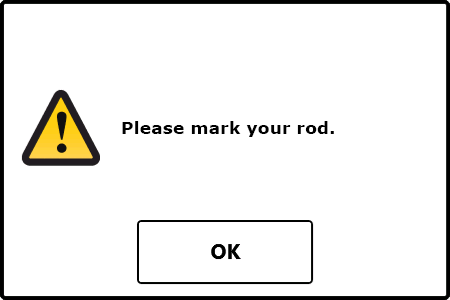
You will use this mark as a visual roll indicator as you continue through these steps.
Tap Start to continue on-screen prompts completing one revolution for each rotation command (three total).
If any rotation is not completed within the prescribed time, or if any rotation continues for more than one full revolution, the transmitter band change is canceled.
When the procedure is finished, the transmitter changes bands.
The locator operator should now change to the other paired and calibrated band.
If the locator operator has not calibrated the second band, depth readings will not be correct.
Tap Exit, then Main menu.
Tap XR again in the Applications tab to close it.
Tap Home to view transmitter data.
When starting an R1 bore plan in a pit, the Rod 0 reading must be taken with the drill head halfway into the pit's wall.
To start a bore plan in a pit, take the Rod 0 reading with the drill head halfway into the pit wall. Compare the first rod's length and the pitch reading with the R1 plan. Modify the plan in the R1 App, if necessary.
If a second rod is required to reach the pit wall, measure how much of the second rod remains when the drill head is halfway into the wall of the pit and record it as the First Rod Length.
If a second rod is required, it is important to remember that the Rod 1 of the bore plan is actually Rod 2.
- First rod length
- Entry depth
- Rod 0 pitch
Things You Should Know
Target Steering is intended to maintain a straight path underground with minimum pitch changes.
The DCI target steering * algorithm brings the drill head below the locator at the programmed target depth * at 0 % pitch.
There may be cases where the approximate projected depth is getting increasingly deeper (or shallower) than desired, and the steering indicator ball indicates more steering is required. This is because additional vertical turning may be required to allow the drill head to become level below the locator. These potential discrepancies should be temporary and disappear as the pitch readings approach 0%. See the Troubleshooting Chapter for a detailed explanation.
Once the locating specialist sets a target depth * on the locator, the Aurora automatically opens the Target Steering application.
The flashing Target Steering icon in the Status bar displays as long as the Aurora is receiving target steering information, even if you are on a different screen.
Use the Target Steering app to view whether your current steering is on target.
This screen example shows that the drill head is currently calculated at 4'11" below the horizontal plane of the locator and the target is 15’8” ahead. If the drill head stays on the same pitch, the projected depth at the target will be 4'11".
The further the drill head is from the locator, the less accurate the estimated projected depth can be. This should therefore only be used as an estimate.
- Current depth below locator
- Steering indicator ball * (projected destination on current heading)
- Target (depth set on locator)
- Horizontal distance to target
- Estimated Projected Depth *
Make small steering adjustments as needed to bring the steering indicator ball toward the target.
The closer the drill head is to the locator, the more sensitive the steering indicator will be.
When the steering indicator is centered on the target and surrounded by a green ring, the drill head is correctly positioned to drill toward the target.
This screen shows the drill head correctly aligned to reach the target at 15'8" ahead with an estimated projected depth of 4'11", and the drill head is currently 4'11" below the horizontal plane of the locator.
When the horizontal distance is almost the same as the current depth, ensure the locating specialist moves the locator farther out to continue Target Steering.
If the drill head passes this point, depth and horizontal distance values on the display become invalid.
Tap the Home icon to stop viewing target steering data.
The Target Steering app remains loaded until Aurora is powered off regardless if target steering data is being received.
The "estimated projected depth" in Target Steering is the depth the drill head is projected to be at below the locator when it reaches the destination if the user maintains the current pitch reading.
You can gauge the depth the drill head might be when it reaches the target below the locator. The further the drill head is from the locator, the less accurate the estimated projected depth can be. This should therefore only be used as an estimate.
- Terrain
- Locator Depth *
- Distance
- Pitch
- Estimated Projected Depth *
There may be cases where the estimated projected depth is getting increasingly deeper (or shallower) than desired, and the steering indicator ball indicates more steering is required. This is because additional vertical turning may be required to allow the drill head to become level below the locator. These potential discrepancies should be temporary and disappear as the pitch readings approach 0%. See the Troubleshooting Chapter for a detailed explanation.
A value programmed into the locator, so it can be positioned ahead of the drill head and used as a steering target. The value programmed should be the desired depth of the transmitter when it reaches the point below the locator. If a locator is placed above ground level, such as to provide separation from interference, that height must be added to the target depth.
Note: If using a Falcon Compact Display, only left/right steering information is available. The locator used with the Falcon Compact Display must still have a target depth set. This target depth can be any value.
A value programmed into the locator, so it can be positioned ahead of the transmitter housing and used as a steering target. The value programmed should be the desired depth of the transmitter when it reaches the point below the locator. If a locator is placed above ground level, such as to provide separation from interference, that height must be added to the target depth.
Note: If using a Falcon Compact Display, only left/right steering information is available. The locator used with the Falcon Compact Display must still have a target depth set. This target depth can be any value.
The yellow steering indicator ball on the Aurora shows where the drill head would pass under the locator on its current heading. Use gentle steering corrections to bring the ball onto the target so the drill head passes directly under the locator at the set depth.
The depth the drill head is projected to be at when it reaches the destination below the locator at the current pitch while using Target Steering.
The depth displayed on the locator to the transmitter.
Depth Increase in Inches (cm)
| % slope | Depth increaseinches (cm) | % slope | Depth increase inches (cm) |
|---|---|---|---|
| 31 | 36 (91) | 43 | 47 (119) |
| 32 | 37 (94) | 44 | 48 (122) |
| 33 | 38 (97) | 45 | 49 (124) |
| 34 | 39 (99) | 46 | 50 (127) |
| 35 | 40 (102) | 47 | 51 (130) |
| 36 | 41 (104) | 50 | 54 (137) |
| 37 | 42 (107) | 55 | 58 (147) |
| 38 | 43 (109) | 60 | 62 (157) |
| 39 | 44 (112) | 70 | 69 (175) |
| 40 | 45 (114) | 80 | 75 (191) |
| 41 | 46 (117) | 90 | 80 (203) |
| 42 | 46 (117) | 100 | 85 (216) |
Slopes between 50% and 100% are provided for reference only and do not represent typical drilling conditions. All numbers are based on math only and do not take into account extremely soft or extremely hard soil conditions, which may cause depth values to vary.
Depth Increase in Inches (cm)
| % slope | Depth increase inches (cm) | % slope | Depth increase inches (cm) |
|---|---|---|---|
| 1 | 2 (5) | 16 | 28 (71) |
| 2 | 4 (10) | 17 | 30 (76) |
| 3 | 5 (13) | 18 | 32 (81) |
| 4 | 7 (18) | 19 | 34 (86) |
| 5 | 9 (23) | 20 | 35 (89) |
| 6 | 11 (28) | 21 | 37 (94) |
| 7 | 13 (33) | 22 | 39 (99) |
| 8 | 14 (36) | 23 | 40 (102) |
| 9 | 16 (41) | 24 | 42 (107) |
| 10 | 18 (46) | 25 | 44 (112) |
| 11 | 20 (51) | 26 | 45 (114) |
| 12 | 21 (53) | 27 | 47 (119) |
| 13 | 23 (58) | 28 | 49 (124) |
| 14 | 25 (64) | 29 | 50 (127) |
| 15 | 27 (69) | 30 | 52 (132) |
| % slope | Depth increase inches (cm) | % slope | Depth increase inches (cm) |
|---|---|---|---|
| 31 | 53 (135) | 43 | 71 (180) |
| 32 | 55 (140) | 44 | 72 (183) |
| 33 | 56 (142) | 45 | 74 (188) |
| 34 | 58 (147) | 46 | 75 (191) |
| 35 | 59 (150) | 47 | 77 (196) |
| 36 | 61 (155) | 50 | 80 (203) |
| 37 | 62 (157) | 55 | 87 (221) |
| 38 | 64 (163) | 60 | 93 (236) |
| 39 | 65 (165) | 70 | 103 (262) |
| 40 | 67 (170) | 80 | 112 (284) |
| 41 | 68 (173) | 90 | 120 (305) |
| 42 | 70 (178) | 100 | 127 (323) |
Slopes between 50% and 100% are provided for reference only and do not represent typical drilling conditions. All numbers are based on math only and do not take into account extremely soft or extremely hard soil conditions, which may cause depth values to vary.
The Estimated Projected Depth in Target Steering calculates the estimated depth below the locator if the user maintains the current drill head pitch reading. This allows the user to gauge the depth they might be at once the drill head reaches a position below the locator. The further the drill head is from the locator, the less accurate the estimated projected depth calculation can be. The depth calculation should therefore only be used as an estimate of the projected depth.
When a target depth is specified, the Target Steering algorithm is designed to land the drill head at the desired depth at 0% pitch. To achieve this, in a case where the drill head is below the desired target depth, the drill head may need to “climb” at a pitch with an estimated projected depth that is shallower than the target depth to arrive at the desired target depth early enough to allow for leveling off at 0% pitch. While this is occurring, the steering indicator ball may provide contrary information, which will resolve as the Target Steering algorithm guides the drill head to level off at 0% pitch.
Verify that both units are set to the same telemetry channel.
Under the same locator icon on the Aurora you’ll find a symbol that looks like a cell tower which represents four telemetry channels. These must be set to the same channel for the remote and the locator.
a. To change channels on your locator, toggle down into the main menu and select Settings.
b. Toggle to the telemetry icon and make sure the locator icon matches your remote.
Verify that your display on the drill is set to the correct locator.
To change what locator your remote looks for click the main menu icon and then on the locator icon under Settings.
Verify that your display on the drill and the locator are set to the same World Region.
You can change the World Region on the remote display, but not on the locator.
Check any external antenna on the remote display for damage.
Ensure all internal pins are intact and clean with alcohol if connection points look dirty.
If not already in use, a filtered antenna may be necessary to reduce the effects of interference in the area.
Call DCI for further troubleshooting.
| Country | Allowed Frequency (MHz) | Limitations | Region (legacy) | Region (new) |
|---|---|---|---|---|
| Austria | 458.6, 458.65, 458.7, and 458.75 | Yes* | UK | GB |
| Belgium | 458.6, 458.65, 458.7, and 458.75 | Yes* | UK | GB |
| Bulgaria | 458.6, 458.65, 458.7, and 458.75 | Yes* | UK | GB |
| Croatia | 458.6, 458.65, 458.7, and 458.75 | UK | GB | |
| Cyprus | 458.6, 458.65, 458.7, and 458.75 | UK | GB | |
| Czech Republic | 449.8, 449.85, 449.9, 449.95 | UK | GB | |
| Denmark | 458.6, 458.65, 458.7, and 458.75 | UK | GB | |
| Estonia | 449.8, 449.85, 449.9, and 449.95 | Yes* | ES | ES |
| Finland | 458.6, 458.65,458.7, and 458.75 | UK | GB | |
| France | 458.6, 458.65, 458.7, and 458.75 | UK | GB | |
| Germany | 458.6, 458.65, 458.7, and 458.75 | UK | GB | |
| Greece | 458.6, 458.65, 458.7, and 458.75 | UK | GB | |
| Hungary | 433.65 and 433.70 | Yes* | SW or SU | CH |
| Iceland | 458.6, 458.65, 458.7, and 458.75 | UK | GB |
| Country | Allowed Frequency (MHz) | Limitations | Region (legacy) | Region (new) |
|---|---|---|---|---|
| Ireland | 458.6, 458.65, 458.7, and 458.75 | UK | GB | |
| Italy | 458.6, 458.65, 458.7, and 458.75 | Yes* | UK | GB |
| Latvia | 449.8, 449.85, 449.9, 449.95 | Yes* | UK | GB |
| Liechtenstein | 433.65 and 433.70 | SW or SU | CH | |
| Lithuania | 449.8, 449.85, 449.9, 449.95 | Yes* | UK | GB |
| Luxembourg | 458.6, 458.65, 458.7, and 458.75 | Yes* | UK | GB |
| Malta | 458.6, 458.65, 458.7, and 458.75 | Yes* | UK | GB |
| Netherlands | 451.03 and 451.09 | Yes* | NL | NL |
| Norway | 458.6, 458.65, 458.7, and 458.75 | UK | GB | |
| Poland | 458.6, 458.65, 458.7, and 458.75 | UK | GB | |
| Portugal | 458.1125, 458.125, 458.1375, 458.15 | PT | ||
| Romania | 433.65 and 433.70 | UK | CH | |
| Slovak Republic | 458.6, 458.65, 458.7, and 458.75 | UK | GB | |
| Slovenia | 449.8, 449.85, 449.9, 449.95 | Yes* | UK | GB |
| Spain | 449.8, 449.85, 449.9, and 449.95 | ES | ES | |
| Sweden | 458.6, 458.65, 458.7, and 458.75 | UK | GB | |
| Switzerland | 433.65 and 433.70 | SW or SU | CH |
*Individual user license required–check with your local authority. Unless otherwise noted, the maximum radiated power output is limited to 100m WERP. Please contact DCI at productcompliance@digital-control.com, if additional technical information or translation is required.
The FAR5 contains a BLE Radio with the following specifications: Frequency Bands: 2402-2480 mHz Transmit Power: 0.00135 W EIRP
The AEO2 contains WiFi/BT and Cellular/GPS radios which operate on the following bands:
CE BANDS
GSM900: 880.2 – 914.8 MHz GSM1800: 1710.2 – 1784.8MHz
LTE Band 1: 1920 – 1980 MHz
LTE Band 3: 1710 – 1785 MHz
LTE Band 5: 824 – 849 MHz
LTE Band 7: 2500 – 2570 MHz
LTE Band 8: 880 – 915 MHz
LTE Band 20: 832 – 862 MHz
LTE Band 28: 703 – 748 MHz
LTE Band 38: 2570 – 2620 MHz
LTE Band 40: 2300 – 2400 MHz
LTE Band 41: 2496 – 2690 MHz
Contact
DCI USA
19625 62nd Ave S, Suite B103
Kent, WA USA 98032
DCI@digital-control.com
1.800.288.3610
1.425.251.0559
DCI Australia
2/9 Frinton Street Southport
Queensland 4215 Australia
DCI.Australia@digital-control.com
+61.7.5531.4283
+61.7.5531.2617
DCI China
368 Xingle Road Huacao Town
Minhang District Shanghai 201107, P.R.C
DCI.China@digital-control.com
+86.400.100.8708
+86.21.6432.5186
DCI Europe
Brueckenstraße 2
97828 Marktheidenfeld Germany
DCI.Europe@digital-control.com
+49.9391.810.6100
+49.9391.810.6109
DCI India
Unit No. 1022, 10th Floor DLF Tower B Jasola District Center
New Delhi 110025 India
DCI.India@digital-control.com
+91.11.4507.0444
+91.11.4507.0440
DCI Philippines
404-405 Energy Opt. Bldg Prime St, Madrigal Business Park 2
Alabang Muntinlupa City, Philippines 1780
DCI.Philippines@digital-control.com
(02)79802647
+632-79802647